Petri dish electrolysis is a simple, colorful way to introduce or wrap up many topics in chemistry. Use this activity to introduce reduction-oxidation reactions and electrochemistry. When using it at the beginning of a lesson, you can learn what students already know, while using it at the end can highlight their learning.
Student misconception: Electrolytic cells and voltaic cells are the same thing.
Voltaic cells are devices that can convert chemical energy into electrical energy, generating electricity. These cells are based on spontaneous chemical reactions that cause electrons to move. Examples of voltaic cells include dry cell batteries, lead-acid batteries, and fuel cells.
Electrolytic cells use electricity to drive otherwise nonspontaneous chemical reactions. In electrolytic cells, a chemical change is forced to occur through the application of electricity. AP Chemistry students should be able to apply thermodynamic concepts to generate claims about what happens in either type of cell.
Overview
This simple microscale electrolysis activity yields 2 pure diatomic gases, hydrogen and oxygen, from water in a petri dish. Adding a universal indicator solution to the reaction provides a visual cue for pH changes and helps students make sense of the chemistry happening at each electrode in the petri dish.
Guiding Questions
Observe the pencil lead carefully. What is being formed there? Is it being formed on both? What’s different? If more is being formed on one than the other, what gas do you think is being formed where there’s more? Think about the equation for water, which atom is there more of?
What colors do you observe? What does that color mean? Which ion causes something to be an acid/base? So, if water is being split, what gas is being released and what ion is going into the water?
Background
Electrolysis involves passing a charge through a solution to drive a reaction that is typically nonspontaneous. When the charge is applied to water that contains an electrolyte, the electrical energy causes the water to decompose into the pure diatomic gases of its constituents, hydrogen and oxygen. The balanced chemical equation for this reaction is:
Energy + 2H2O(l) → 2H2(g) + O2(g)
The above reaction is a reduction-oxidation reaction. Hydrogen is reduced in the reaction (from +1 to 0), and oxygen is oxidized (from –2 to 0). Here are the two half-reactions and the energy changes associated with them, expressed as standard electrode potentials (Eo):
Reduction 4H2O(l) + 4e– → 2H2(g) + 4OH–(aq) Eored = 0.00 V
Oxidation 2H2O(l) → O2(g) + 4H+(aq) + 4e– Eoox = –1.23 V
Adding these half-reaction equations gives the overall equation. Adding the standard reduction and oxidation potentials gives a negative value of –1.23 V. A negative value indicates that the reaction is not spontaneous and will occur only when energy is added to the system.
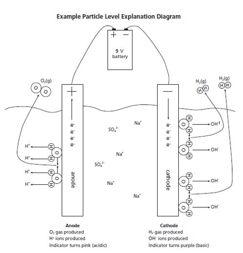
In the experiment, reduction of hydrogen occurs at the cathode (electrode connected to the negative battery terminal), while oxidation of oxygen occurs at the anode (electrode connected to the positive battery terminal). An electrolyte is needed to carry the charge through the solution. Due to the low self-ionization of water, a separate, inert electrolyte is needed. The electrolyte in this activity is sodium sulfate, Na2SO4. This salt dissolves in water to form sodium and sulfate ions.
The addition of Bogen universal indicator solution lets students monitor the reaction’s progress. When the experiment begins, the solution is green because the sodium sulfate solution has a pH of 7 and Bogen’s color at this pH is green. As the reaction progresses, violet develops at the cathode as hydroxide ions form and the solution becomes basic. At the anode, yellow or orange develops as hydrogen ions form and the solution becomes acidic. In addition, bubbles of hydrogen gas form at the cathode, and bubbles of oxygen gas form at the anode. If the hydrogen and oxygen gas were collected at each electrode, the volumes would be 2:1 respectively, as indicated by the molar ratios of the balanced equation.
Multiple colors appear as hydrogen ions and hydroxide ions spread through solution, creating pockets of locally different pH. Bogen universal indicator contains the acid-base indicators methyl red, bromothymol blue, and phenolphthalein to create a range of colors from pH 4 to 10. Refer to the color chart provided with the solution and to the table below to identify the pH values.
| pH | Color |
|---|---|
| 4 | Red |
| 5 | Orange |
| 6 | Yellow |
| 7 | Green |
| 8 | Light Blue |
| 9 | Dark Blue |
| 10 | Violet |
Tip: Although most water-soluble salts make good electrolytes, chloride salts (e.g., sodium chloride and potassium chloride) generate small amounts of chlorine gas at the anode, because the oxidation of chloride ion is energetically competitive with the oxidation of oxygen. The chlorine gas may corrode the electrode. For best results, choose inert electrolytes such as sulfate salts.
Extension Activity
Have students use words or pictures to explain and illustrate electrolysis of water on a molecular level. Results should be similar to the example below.


